This tech tip describes the default backbox image and how to make it more interactive. We also look at the LEDs on the backbox.
Unity supports up to eight Displays. The Unity Editor numbers Displays from 1 to 8, whereas C# scripts use 0 to 7. In this discussion, we use the Editor's numbering convention (1–8).
The P3 uses three Displays:
Display | Description |
1 | Playfield |
2 | Backbox |
8 | LED Simulation (only exists in the simulator) |
Unity activates Display 1 by default. The other Displays are activated in Setup (the base class of P3SASetup).
The mini LCD screens on the modules are driven by a Raspberry Pi, not directly by Unity. The AppLauncher can show a fixed image from the application’s LauncherMedia/Icons/Auxiliary directory. See the Deployment section of the SDK Developer Guide for details on LauncherMedia. If you want to display something more dynamic, you will need to contact Multimorphic support. They chose not to make this API part of the SDK and there is no public documentation for it.
In the Unity Editor, you can change which Display is shown when the app is running. For example, click on Display 1 in the Game view and select Display 2 in the dropdown to show the backbox. The image will look stretched because the playfield is portrait (1080x1920) but the backbox is landscape (1920x1080). You can fix this by creating a new resolution in the Game window. Click on Standalone (1080x1920), click on the + button at the bottom of the dropdown list, set the Label to Landscape, the Width to 1920, the Height to 1080, and click OK. Now the backbox displays correctly. If you go back to Display 1, the playfield is now stretched. You will need to change the resolution back to Standalone.
It is tempting to customize the Unity Layout to have two Game views side by side, but there is a bug in Unity 5.6.7 when two Game views have different resolutions. Only one of them will display correctly. It might not work well for the playfield and backbox together, but you could make it work for the playfield side by side with the LED simulation.
To see anything on a Display, you need a Camera with its “Target Display” property set to that Display. This table lists the Cameras defined in each scene of P3SampleApp.
Scene | Camera | Target Display | Note |
Bootstrap | Main Camera | 1 | |
Attract | Main Camera SecondDisplayCamera LED_Camera_SimulationOnly | 1 2 8 | Always disabled Exists in simulator only |
Home | Main Camera LED_Camera_SimulationOnly | 1 8 | Exists in simulator only |
The SecondDisplayCamera is disabled and never used in P3SampleApp. The Camera for the backbox Display is created at runtime.
When multiple Cameras have the same “Target Display”, the Camera with the lowest Depth is rendered first, with the higher-Depth cameras drawing on top. The Depth is a property on the Camera.
A Canvas is the root container for Unity UI elements. All UI elements must be placed within a Canvas to be rendered. A Canvas can be assigned to a specific “Target Display” to control which Display the UI appears on.
The Canvas “Render Mode” determines how the UI is shown. Choose “Screen Space - Overlay” to render the UI flat on the same plane as the screen. Choose “Screen Space - Camera” to place the Canvas at a given distance in front of the specified Camera within the scene.
A scene can contain multiple Canvases targeting the same or different Displays.
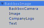
The BackboxImage prefab is located at Assets/Resources/Prefabs/Framework/BackboxImage.prefab
This prefab is a Canvas with “Target Display” set to 2. It is the default content for the backbox Display.
SceneController has a boolean parameter named “Show Default Backbox” to specify whether the BackboxImage is used. The SceneControllers in P3SampleApp have “Show Default Backbox” set to true.
If the default backbox is disabled in the scene, the SceneController destroys the BackboxImage (if present).
If the default backbox is enabled for the scene, the SceneController reuses the existing one, or creates a new one with the DontDestroyOnLoad flag. The CompanyLogo is displayed during the Bootstrap scene. For other scenes, the file matching ./LauncherMedia/Icons/Backbox/*.png or *.jpg is shown instead. If the file does not exist, the app name is shown as Text. In P3SampleApp, the .png file exists, although it contains only the app name and two black stripes.
Even though the BackboxCamera’s Culling Mask includes Everything, the scene objects are not visible because the Canvas renders on top of all scene objects.
BackboxImage is limited to displaying a static image. To show dynamic content, you must disable it and create your own Camera with “Target Display” set to 2.
It might be tempting to use one scene for the playfield and another for the backbox. Unity supports this through additive scene loading, which allows multiple scenes to be active simultaneously. However, this approach is not recommended with the P3 SDK, as the SDK expects a single active scene and behavior is otherwise undefined.
In a P3 application, the active scene must contain the content for all Unity displays. The challenge is determining how to prevent playfield objects from appearing on the backbox display, and vice versa.
One effective solution is to use a Canvas that covers the entire screen. Set its “Render Mode” to “Screen Space – Overlay” and its “Target Display” to 2. This approach is limited to 2D content.
Another solution is to use Layers and Culling Masks, which support both 2D and 3D content. See the next section.
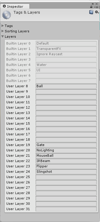
To display different content on Display 1 versus Display 2, you assign the objects to different Layers. Unity supports up to 32 Layers, though you must not use Layer 31. To see the existing Layers in P3SampleApp:
The Tags and Layers window appears.
Create one or more Layers for the backbox. For example, enter Backbox next to User Layer 15.
In the Camera, you set the Culling Mask to the Layers you want to display. For example, on the Main Camera, you may select all Layers except the Backbox Layer. Conversely, on your Backbox Camera, you select only the Backbox Layer. It is not necessary to select the UI Layer since it is always on regardless of the Culling Mask.
The backbox has 3 LEDs:
LED Name | Description |
backboxP3 | P3 logo |
playfield | LED strip shining down on the playfield |
backbox | Illuminates the translite from behind |
By default, BaseAppMode creates BackboxColorsMode, which sets the colors of these LEDs based on nine GameAttributes.
LED Name | GameAttributes |
backboxP3 | P3Red, P3Green, P3Blue |
playfield | PFRed, PFGreen, PFBlue |
backbox | BackboxRed, BackboxGreen, BackboxBlue |
BackboxColorsMode responds to these mode events:
Event | Event Data |
Evt_ChangePFColor | ushort[4] color |
Evt_ChangeBackboxColor | ushort[4] color |
Evt_ChangeBackboxP3Color | ushort[4] color |
Evt_SetBackboxP3Color | ushort[4] color |
Evt_SetBackboxColor | ushort[4] color |
Evt_SetPFColor | ushort[4] color |
Evt_EnableBackboxLEDs | bool |
Evt_SetBackboxP3Color, Evt_SetBackboxColor, and Evt_SetPFColor are posted by SettingsMode. The other events are not used by the SDK or P3SampleApp.
It is often necessary to override BackboxColorsMode to gain control of the “playfield” LED strip because it has a profound impact on the lighting mood of the application.
BackboxColorsMode can be overridden with a mode at priority 411 or higher. This corresponds to Priorities.PRIORITY_BACKBOX_COLORS + 1. The mode can control the desired LEDs and let BackboxColorsMode control the other LEDs.
Another possibility is to disable BackboxColorsMode completely by setting useBackboxColorsMode to false in the <AppCode>BaseGameMode constructor. For P3SampleApp, that would be in P3SABaseGameMode. The application must take control of the 3 LEDs since BackboxColorsMode will no longer be running. The application can reuse the 9 GameAttributes and the 7 events if applicable, but there is a good chance they are no longer relevant.
The RGB LED Speaker Panel kit is an optional mod that adds LEDs around the backbox speakers. The application can control the speaker LEDs by creating LEDScripts for the following LEDs:
speakerLeft0 .. speakerLeft60
speakerRight0 .. speakerRight60
These LEDs are part of the P3 base platform module definition whether the kit is installed or not. If you control these LEDs and the kit is not installed, no adverse effects will occur. See the Speaker Panel LEDs tech tip for more information.
The base platform module definition also declares these outer cabinet LEDs:
backboxBack0 .. backboxBack82
backboxBottom0 .. backboxBottom17
backboxFront0 .. backboxFront89
backboxTop0 .. backboxTop27
cabinetBack0 .. cabinetBack82
cabinetBottom0 .. cabinetBottom171
cabinetFront0 .. cabinetFront20
cabinetTop0 .. cabinetTop155
These LEDs are not present on the production version of the P3 machine. They belong to LEDStrings that were used to decorate the two prototypes built for Dave & Buster’s. You can see these LEDs in this video of the unreleased “Heads Up” game. Multimorphic does not have a commercial offering for the exterior lighting of the backbox or cabinet.
It is best to explicitly exclude those LEDs in lightshows that iterate over all the LEDs in the p3.LEDs[] collection.